Drive
Features
- Pullup GPIO
- I2C breakout
- Power distribution from XT60 to XT30
- USB-C
- CANBus
Authors
- Shin Umeda
Active Revisions
- V6
Summary
The drive board houses a micromod unit, and interfaces it with the drive motors and limit switches. There are connectors for XT30 and XT60 power connectors intended to distribute power from the (Hub board)[hub.md] to the motors. The power connections are only connected via ground, and otherwise do not interact with the circuit overall.
Design Notes
G0 is known to be unusable during JTAG debugging on the STM micromods because G0 is also a JTAG pin. The SPI pins connect to SPI0, which are not connected to anything on the STM micromods. There is an additional I2C connector that is not currently used for anything.
Known Defects
- JTAG does not have relevant pullup/pulldown resistors. See https://community.nxp.com/t5/S32K/S32K-JTAG-SWD-Pull-Ups-and-Pull-Downs/m-p/843921
- The 5V and GND on the bottom 4-pin connector are swapped on the silkscreen.
Additional Resources
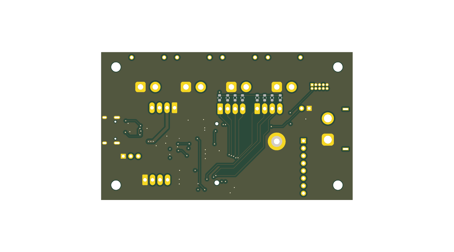
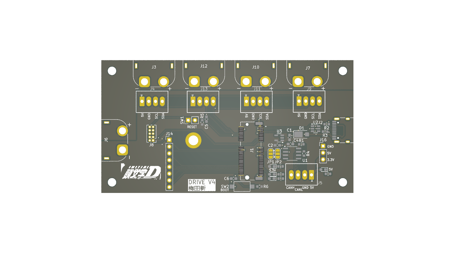
PCB Images